Comparing low frequency (100 kHz) plasma systems to higher frequency (13.56 MHz) plasma systems
We frequently (no pun intended) have Customers that want to know why we offer 100 kHz systems as well as 13.56 MHz plasma systems, and what is the difference of each. Dr. Daniel Dobkin, coauthor of Principals of Chemical Vapor Deposition (Authors: Dobkin, Daniel, Zuraw, M.K.) https://www.springer.com/us/book/9781402012488 has been good enough to share some comments on this question.
Summary: some generalizations that can be made:
• 100 kHz excitation is not “DC-like”, in the sense that the plasma persists throughout the RF cycle — but the frequency is typically much lower than (1/sheath transit time). Thus, ions that enter the sheath near the wafers will acquire the full energy associated with the RF voltage, minus any losses to scattering with neutral molecules or atoms. The sheath voltage is small when the electrode in question is the anode, but large when it is the cathode. And 100 kHz electrode voltages are typically much larger than 13 MHz voltages, because of the mechanisms that support the plasma. A low-frequency plasma generally depends on secondary emission at surfaces: that is, an ion strikes the surface and generates one or more secondary electrons. The electrons are repelled from the cathode and accelerated into the plasma by the sheath voltage. When they reach the plasma region, they have enough energy to ionize molecules, and the voltage increases until this secondary ionization makes up for the ions lost at the sheath edges. At 100 kHz this is the main mechanism for ionization and thus for sustaining the plasma.
• At 13 MHz and above, the sheath edge is moving rapidly. This has the benefit of creating a large capacitive current that has to flow through the plasma to alternately charge and discharge the sheaths. That displacement current can help ionize molecules, keeping the plasma alive with a lower sheath voltage. The resulting electron density in a high-frequency plasma is typically quite a bit higher than a low-frequency plasma, and of course the ion density has to equal the electron density in the bulk of the plasma. In addition, the sheath transit time is now typically longer than an RF cycle, so instead of alternating between very energetic ions and very gentle ions, the ion energy striking the surfaces tends to be fairly uniform in time.
Here are excerpts from the book mentioned above:
1. THE LOW-PRESSURE COLD-PLASMA STATE
The most commonly encountered plasma in CVD applications is the capacitive or “RF diode” plasma. A simplified view of such a reactor might look like figure 6-1. In this figure ne = ni is the plasma density; typical values are around 108 to 1010 /cm3, compared to a neutral density of 3×10¹⁵/cm3 at 100 mTorr. (The ion and electron densities are equal to maintain charge neutrality in the bulk plasma.)
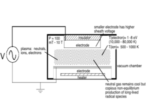
Figure 1. Simplified view of a generic capacitively-excited plasma
The plasma is excited and sustained by applying a voltage – typically AC or RF, 60 Hz to many MHz — between the two electrodes. The “capacitive” moniker arises from the nature of the coupling to the plasma. The plasma forms “sheaths”, regions of very low electron density, next to solid surfaces: the RF voltage appears mostly across these sheaths as if they were the dielectric region of a capacitor, with the electrode and the plasma forming the two plates.
The system pressure for CVD applications is usually between about 100 mTorr and 10 Torr. The electrodes are typically cylindrical, with the separation between the two electrodes small compared to the electrode diameter. The electrode “gap” is an important parameter; it varies from about 0.5 cm to 10 cm, generally getting smaller for higher pressure operation. Typical gaps are a few hundred times the mean free path, so electrons undergo many collisions but do not have time to transfer their energy to the neutral gas. However, practical limitations on chamber size generally lead to increasing ratios, and “hotter” plasmas, at higher pressures. Thus, a gap of 5 cm, which is very easy to build, corresponds to about 100 mean free paths at 100 mT, but to achieve the same relative separation at 10 Torr one would need to separate the electrodes by only 0.5 mm or 500 microns: a very challenging mechanical task if the diameter is comparable to the size of a wafer! Typical electron temperatures are around 5 eV. Electron temperature varies weakly with other parameters: it is dominated by the requirement that the electrons provide enough ions to keep the plasma going.
The ion density is equal to the electron density in the plasma, to ensure overall balance of charge: the density of electrons and ions is just known as the plasma density. (This statement is true for “electropositive” plasmas, in which only positive ions are present in significant numbers. “Electronegative” plasmas result when attachment of electrons to form negative ions is important; such plasmas have very different properties. They are particularly important in etching applications, but less frequently encountered in deposition.) Most atoms and molecules have ionization energies of around 5-20 eV (see table 6-1), but in a typical low-pressure plasma around 100 eV of total energy input is required to produce an ion and a new electron, due to all the energy lost to non-ionizing collisions, excitation/de-excitation, and inefficient energy transfer. The ions are mainly lost by diffusion to the walls in a low-pressure plasma.
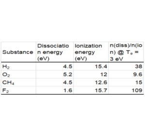
6-1. Dissociation and ionization energies for some gases commonly encountered in semiconductor processing. n(diss) is the density of electrons with sufficient energy for dissociation; n(ion) the density of electrons able to ionize.
The plasma density is set by the balance between the input power, which heats the electrons and provides energy to ionize, and the loss of ions to the walls. Plasma density in typical capacitive plasmas is very “low”: the fractional ionization is only about 0.01% (1 molecule in 10,000 is ionized). Fractional excitation can be much higher, since excitation and dissociation usually require less energy than ionization (table 6-1). The electrons are distributed in a vaguely Maxwellian fashion, as exp (-E/kTe); thus there are many more electrons with energies of e.g. 8 or 10 eV, able to dissociate, than there are at 15-25 eV driving ionization processes.
As depicted in figure 6-1, electropositive plasmas form sheaths of low electron density – also known as dark spaces from their visual appearance – near solid surfaces. In figure 6-2 we show a cross-sectional diagram of the electrostatic potential in a plasma, similar to an energy band diagram for a semiconductor device. Ions roll “down hill” in the sheath regions, acquiring energy which is dissipated when they strike the walls. Electrons float bubble-like upwards, and are thus confined by the potential away from the sheath regions, which therefore have few electrons. The plasma is always the most positive object in the system. Occasionally an ion striking the wall surface knocks off an electron – a secondary – which then is accelerated into the plasma by the sheath electric field.
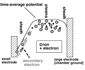
Figure 6-2. Time-averaged electrostatic potential in a capacitive plasma; electrons rise towards positive potential, ions fall towards negative potentials.
An electrically isolated object in the plasma will have a sheath around it, since the mobile electrons are lost more readily by diffusion to the surface, giving the plasma an increasing net positive charge until a sheath forms to ensure charge balance. Such sheaths have a potential of typically 10-25 volts. The sheath potential at the excited electrodes is much larger: it varies during the RF cycle, with peak values of several hundred volts often present.
Because sheaths are present at all surfaces, the substrate surface in a plasma is likely to be bombarded with ions, whose kinetic energy varies from a few 10’s to several hundred eV, in addition to the usual flux of neutral molecules, and lots of neutral but reactive radicals. Ions in the sheath can also undergo charge-transfer collisions, losing their net charge but not their kinetic energy; thus very energetic neutrals may also be present (figure 6-3).

Fig-3. Surfaces exposed to the plasma are bombarded by ions and radicals as well as the usual thermal flux of neutral species.
The actual potential across the sheaths varies with time in order to add up to the applied RF voltage (very little voltage typically appears across the plasma itself). The plasma is always more positive than either of the electrodes, as otherwise electrons would rapidly escape from the plasma. Thus one sheath grows and the other sheath shrinks as we proceed through the RF cycle. Figure 6-4 depicts the situation. At t=0, the top electrode has a “floating” sheath with only a few volts across it, allowing electron current to flow (to neutralize the ions that struck the surface during the remainder of the cycle), while the bottom electrode has a sheath with e.g. 240 V potential drop, causing energetic ion bombardment of the surface. A half cycle later (t=1/2) the sheath on the bottom electrode is small, and that on the top electrode is large. Note that the plasma potential is large and positive at the quarter-cycle point where no instantaneous voltage is applied (at least for reasonably high RF frequencies; for AC excitation at 10’s of Hz, the ions and electrons have time to leak out and the plasma density varies with the AC cycle. More about the effect of excitation frequency can be found in section 3.2 below.).
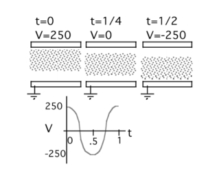
Figure 6-4. Instantaneous potential in an RF plasma; time t is normalized to the RF cycle time.
2. KEY PARAMETERS FOR CAPACITIVE PLASMA BEHAVIOR
2.1 Chamber Pressure
The voltage necessary to initiate a discharge is roughly a function of the product of the spacing between electrodes and the pressure. The minimum voltage occurs at a product of about 1 Torr-cm. At higher pressures, the discharge voltage increases, making it difficult to start the plasma if the electrode spacing is large. The relationship between breakdown voltage and pressure-distance product is commonly known as the Paschen curve for a particular gas; an example for air is shown in figure 6-5.
At very low pressure (or more properly small pressure-distance product), there are too few collisions and electrons traverse the chamber and strike the walls without ionizing. Again the voltage for initiating the discharge increases. For typical chamber geometries, it is very difficult to initiate a capacitive discharge at pressures less than 10-20 mTorr, though it is often possible to “strike” the discharge at higher pressure and then operate at only a few mTorr. This high breakdown voltage is exploited in making dark space shields, grounded plates placed within a few mm of a powered electrode to localize the plasma above the electrode.
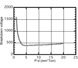
Figure 6-5. Breakdown voltage vs. P-d product for air (after Basic Data of Plasma Physics, S. Brown)
The electron and ion diffusivities increase just like neutral diffusivities as roughly (1/P). (The diffusion of electrons and ions is, however, coupled; we’ll discuss this ambipolar diffusion later.) Thus at pressures of 10’s of mTorr, electrons diffuse readily and the plasma tends to spread through the reactor; at pressures of a few Torr and above plasmas are generally confined to the regions where the electric fields heat the electrons.
Recombination of electrons and ions requires a third body (e.g. another molecule) to carry away the energy of ionization — otherwise, the electron will just fly off again. Since the likelihood of a third body being around just when needed goes up with pressure, recombination in the gas is very slow at low pressures (a few Torr and below) but can be important in high pressure plasmas (greater than about 10 Torr for typical geometries).
2.2 Time and Frequency: DC, AC, RF, Microwave
What frequency of excitation should one apply to the electrodes to create a plasma? What difference does it make?
As we’ve noted, electrons and ions are lost primarily to the walls at pressures of a few Torr or less, rather than to recombination in the gas phase. For chamber sizes of a few cm (shortest length) the electrons are gone in 20-100 µsec, corresponding to a characteristic frequency of 10,000 to 50,000 Hz. Thus excitation frequencies f << 10 KHz can be regarded as “DC”: the plasma density fluctuates widely during the cycle. For very low frequencies the plasma can be regarded as turning on and off each cycle. For f >> 100 KHz, there isn’t enough time for electrons and ions to be lost during the differing parts of the sinusoidal cycle, and the plasma can be regarded as continuously present.
Typical ion velocities are similar to typical molecular thermal velocities, on the order of 105 cm/s. For a typical sheath thicknesses of 0.5 – 2.5 mm, ion transit times are 0.5 – 2.5 µsec. Therefore if the frequency of excitation f < 1 MHz, ions cross the sheath in < 1 RF cycle, and their energies reflect the instantaneous sheath potential. When f > 10 MHz, the ions take many RF cycles to cross the sheath, and their kinetic energy depends on the time-average potential. Thus at low frequencies (<1 MHz), ion energies can vary from very small values (when the sheath is small ) to energies equal to the peak RF voltage. At a more typical RF frequency of 13.56 MHz, the range in ion energies is much reduced, because the ions gain energy over several RF cycles. An example of the resulting ion energy distributions, calculated for argon gas, is shown in figure 6-6. The “low” frequency plasma shows peaks at near zero voltage (the floating sheath portion of the RF cycle) and >200 V (where almost all the voltage is on one sheath). The “high” (13.6 MHz) frequency excitation gives a narrow range of ion energies as the ions experience the average of many RF cycles during their transit of the sheath.
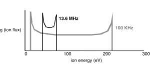
Figure-6. Calculated ion energy distribution function (number of ions vs. ion energy) for argon at “high” and “low” frequencies; data from Dry Etching for VLSI, van Roosmalen et. al.
The frequency of excitation also determines what mechanisms come into play in creating the ions which keep the plasma lit. The plasma is sustained by hot electrons which strike molecules to knock off another electron, creating an ion. At very low frequencies (< 10 KHz) the mechanism for creating these hot electrons is very similar to that operating in DC plasmas: the large sheath voltage present at the cathode accelerates the secondary electrons, which gain enough energy to ionize atoms or molecules in the plasma (figure 6-7). This is an inefficient process: very large sheath voltages (400-700 V) are required, and much of the electron energy is dissipated in non-ionizing collisions.
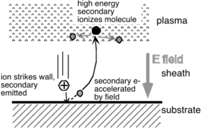
Figure-7. Ionization from secondary electron emission
As frequency increases into the MHz range, two new mechanisms for transferring energy to electrons become important. First, the change in sheath sizes with each RF cycle requires that charge move back and forth through the plasma — that is, that a displacement current flow must exist (figure 6-8(a)). The current can be quite significant; for example, consider an RF voltage of 200 V at a frequency = 8.5×10⁷ radians/second (13.6 MHz). If we assume the sheath is 5 mm thick on average and simple treat it as a parallel plate capacitor, we obtain a displacement current density |J| = V C = 3 mA/cm2, much larger than the sheath ion currents present in typical capacitive plasmas. This displacement current, like any other current, encounters some resistance as it flows in the plasma, and leads to a voltage and thus heat dissipation through P = V*I. Since the current is proportional to frequency, and the power is proportional to the square of the current, the amount of power dissipated scales as the square of the frequency. Displacement current heating takes place in the bulk plasma, and is most important at high pressures and large electrode gaps.
The motion of the sheath is itself significant: a 1 cm wide sheath growing and shrinking 10,000,000 times per second must be moving at about 107 cm/second. Such a velocity is quite comparable to electron thermal velocities. Electrons in the plasma can scatter from the sheath and gain energy (figure 6-8(b)). Naturally, they can also give up energy to the sheath when it is moving away from them, but the number of electrons encountering the sheath is higher when it moves into the plasma than when it moves out. Sheath reflection is localized near the moving sheath edge, and is especially important for low pressure plasmas (10’s to 100’s of mTorr). It also scales as the square of the frequency.
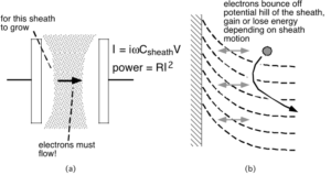
Figure-8. High-frequency electron heating mechanisms: (a) displacement current (b) sheath energy transfer
We can see why one might wish to excite a plasma with a frequency of a few tens of MHz. In fact, it is very common for an excitation frequency of 13.56 MHz to be employed in plasma processing. This frequency, and some of its harmonics, are reserved for industrial as opposed to communications use by the FCC in the United States. While there is no underlying physical reason to prefer 13.56 MHz as opposed to, say, 12 MHz or 14.5 MHz, the powerful influence of the economics of scale has made power supplies and matching networks more widely available at lower cost for this standard frequency than for others nearby.
Microwave frequencies can also be employed to excite plasmas. Several new issues arise; a parallel-plate reactor is not an appropriate design in this case. We’ll discuss microwave plasmas in more detail when we look at alternative excitation approaches in section 4. [not included in this excerpt…]
2.3 Chamber Geometry
In many practical reactors, one electrode is “grounded” — connected to the chamber wall, which is normally connected to “true” ground for safety reasons. In this case, the area of one electrode is much larger than that of the other (figure 6-9(a)). In such reactors, it is empirically found that most of the RF potential appears across the sheath near the smaller electrode. Simple theoretical arguments predict a dependence on the fourth power of the electrode area, but a quadratic dependence is more typically observed in practice:
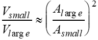
[6.1]where the V’s are time-average sheath voltages and the A’s are areas.
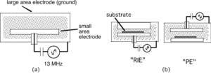
Figure-9. (a) Typical reactor configuration with outer walls grounded (b) “Reactive Ion Etching” and “Plasma Etching” configurations.
Typical reactor configuration with outer walls grounded (b) “Reactive Ion Etching” and “Plasma Etching” configurations.
As a consequence, larger peak ion energies are observed on a substrate mounted on the smaller electrode. This configuration is sometimes referred to as a “reactive ion etch” configuration, and distinguished from the “plasma etching” configuration with either substrates mounted on the large area, or equal area electrodes (figure 6-9(b)). Many plasma CVD processes operate at a high enough pressure (a few Torr) that the plasma is mostly contained between the electrodes, so that they are effectively symmetric reactors, even if the wall area is actually large.
In a conventional reactor, we can increase the RF power to get a higher ion bombardment energy, but the plasma density will also increase. We can’t adjust these two parameters independently. An additional degree of flexibility can often be obtained by providing more than one frequency of excitation of a capacitive plasma. A typical approach is shown schematically in figure 6-10. Two separate power supplies are employed, each attached to one electrode. Filtering is employed to minimize the interaction between the two signals: in this case, we’ve shown an inductor that grounds the top electrode at 100 KHz, while appearing to be a high impedance for a 13 MHz signal. Similarly, a capacitor is used to ground the lower electrode for high frequency signals. This configuration is sometimes known as a triode reactor. Alternative configurations where both supplies are connected to the same electrode can also be employed.
Figure-10. “Triode” or “dual frequency” reactor configuration
To a fair approximation, the high frequency power controls the plasma density, due to the more efficient displacement current and sheath heating mechanisms mentioned above. The low frequency excitation influences the peak ion bombardment energy (section 3.2). Therefore, the user has some ability to independently adjust the ion bombardment energy and the plasma density, which is not very easy with a single excitation energy. Reactors of this design have found applications in both CVD and plasma etching. In particular, adjustment of the low-frequency / high-frequency power split allows control of deposited film stress, valuable for silicon oxides and nitrides.
SOURCE: Principles of Chemical Vapor Deposition, Daniel M. Dobkin and Michael K. Zuraw, Springer-Verlag 2003, B00866EIQ2
Here is where you can purchase this book: Dr. Daniel Dobkin, coauthor of Principals of Chemical Vapor Deposition (Authors: Dobkin, Daniel, Zuraw, M.K.) https://www.springer.com/us/book/9781402012488
For more information on our 100 kHz GLOW plasma system click here
For more information on our 13.56 MHz systems, click here
Our sincere thanks to Dr. Dobkin for sharing his knowledge and time. You can visit his web site…click here